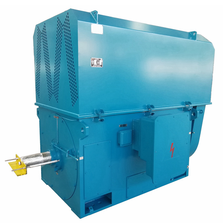
Low Voltage Slip Ring Motors and 6.6 kV slip ring motors operate at different voltage levels, but both require disciplined inspection when winding trouble appears. This guide explains how to identify symptoms, carry out safe diagnostic steps, and decide whether a motor needs repair or replacement. It is written for maintenance teams, plant engineers, and purchasing groups who need useful evidence before approving work.
Searchers troubleshooting a 6.6 kV motor generally need more than a list of possible faults. They need a safe sequence of checks, guidance on what test results mean, and practical ways to prevent repeat failures and extended downtime. Follow the motor manufacturer instructions and applicable site electrical safety rules throughout.
A 6.6 kV motor can retain dangerous electrical energy even after it has been switched off. Only authorized, qualified personnel should isolate and test it. Apply your site's lockout and tagout procedure, verify the correct equipment is isolated, prove the voltage tester before and after use, test for absence of voltage, and discharge and ground conductors as required by site rules. Treat all winding tests as potentially hazardous and use the manufacturer's procedure.
Do not remove access covers, disconnect leads, or touch slip ring or winding connections until the equipment is confirmed safe. If isolation cannot be confirmed, stop and contact the site's electrical safety authority.
Before disturbing connections, document the conditions surrounding the failure. This information can distinguish an electrical winding problem from a mechanical, cooling, or operating issue.
Preserve photographs and relay records before resetting devices or cleaning evidence. A purchasing group can use this record to compare repair proposals and avoid approving a repeat repair without a documented cause.
Choose instruments rated for the motor, test method, and work environment. A qualified electrical testing team should confirm instrument condition, calibration status, test leads, and the manufacturer's limits before use.
Do not select a test voltage or acceptance limit from a generic online table. Use the motor documentation, applicable standards, condition history, and advice from a qualified motor test specialist. Record instrument identification, calibration date, ambient temperature, connection arrangement, and test conditions with every result.
Review trip records and operator observations, then confirm whether the reported problem is a winding fault, a supply fault, a rotor circuit fault, or a mechanical issue. Check the protection device indications and event history before resetting them. Compare phase currents, voltage imbalance, temperature readings, and trip timing with previous operating records where available. Do not restart the motor simply to reproduce a suspected winding fault.
With the motor safely isolated and grounded, inspect accessible terminal boxes, cable terminations, lead supports, insulation surfaces, and the area around the slip rings. Look for discoloration, tracking, carbon dust, oil or moisture contamination, loose hardware, cracked insulation, blocked ventilation, and signs of localized heating. Photograph defects and label disconnected leads before any disassembly. Do not scrape or clean away evidence before documenting it.
Inspect the brush gear, brushes, holders, springs, flexible shunts, ring surfaces, and rotor connections according to the manufacturer's maintenance instructions. Check for uneven brush wear, poor brush contact, excessive dust, grooving, pitting, contamination, or evidence of arcing. A rotor circuit defect can cause poor starting torque, excessive starting time, current imbalance, or repeated protection operation and may be mistaken for a stator winding failure.
Do not assume that replacing brushes will correct the cause. Record brush grade and dimensions, spring condition, ring condition, and evidence of uneven contact. Ask a motor specialist to assess ring surface condition and permissible repair dimensions.
After confirming the test setup and isolating external parallel paths as required, measure winding resistance using the motor manufacturer's procedure. Record the connection points, winding temperature, and each reading. Compare phase values after accounting for temperature and the measurement method. A significant difference can indicate a poor connection, an open circuit, a damaged joint, or a winding defect, but it is not proof of a specific failure on its own.
Use an insulation resistance test only when approved for the motor and its connected accessories. Disconnect equipment that could be damaged by the test and follow the specified test voltage, duration, discharge, and grounding procedure. Record winding temperature and humidity where required. Compare results with the manufacturer's criteria and previous readings. A low or changing value can be associated with moisture, contamination, damaged insulation, or a connection issue; it must be interpreted in context by a qualified person.
If the fault remains uncertain, have a qualified motor test provider select additional tests. Depending on the design and evidence, this may include polarization index, dielectric loss or power factor, partial discharge, rotor circuit assessment, or surge comparison testing. These tests have different purposes and risks. Do not apply them automatically or use them to justify continued operation without an engineering assessment.
Review visual findings, test measurements, protection records, operating history, and the motor's prior condition as a single evidence set. Identify what is confirmed, what is suspected, and what remains unknown. If the evidence points to a winding defect, determine whether a controlled repair assessment, full rewind, rotor repair, or replacement evaluation is appropriate. Obtain a written scope that identifies the failure location, proposed work, acceptance tests, and warranty terms.
Voltage imbalance, unsuitable starting conditions, repeated starts, switching transients, protection settings, and supply disturbances can increase winding stress. Check event records and starting duty against the motor rating and application. Do not change protection settings to suppress repeated trips without an engineering review.
Overload, restricted ventilation, failed cooling components, high ambient temperature, dust, oil, and moisture can degrade insulation over time. Inspect cooling paths and maintenance history, and compare temperature records with the motor's design limits. Correct the source of contamination or overheating before returning a repaired motor to service.
Misalignment, bearing problems, foundation movement, unbalanced loads, loose connections, or rotor movement can damage leads and insulation. Review vibration readings, coupling and bearing history, mounting condition, and terminal tightness using the manufacturer's torque requirements. Avoid tightening electrical connections by guesswork.
Poor brush contact, incorrect brush grade, uneven wear, damaged rings, excessive contamination, or a rotor connection defect can create arcing and abnormal heating. Record the condition and seek a specialist assessment where rings are grooved, cracked, out of round, or beyond allowable limits. A winding repair without correcting a related rotor circuit problem may lead to another failure.
When a result is unstable, contradictory, or outside the manufacturer's acceptance criteria, stop and escalate it. A cautious hold is generally less costly than worsening insulation damage or causing an unplanned outage.
Purchasing teams need enough evidence to compare bids fairly. Ask each supplier to state the confirmed failure mode, inspection findings, test methods, proposed repair scope, materials, workmanship standard, and acceptance criteria. Confirm whether the quotation includes rotor and slip ring work, bearing or cooling repairs, balancing, transportation, and site commissioning.
A rewind can be appropriate when the core and mechanical components remain serviceable and the repair scope is properly controlled. Replacement may be preferable when damage is extensive, repeat failures have occurred, efficiency or process requirements have changed, or repair quality and availability cannot be demonstrated. Make the decision with engineering, maintenance, operations, and purchasing input.
Before energizing a repaired motor, verify that the repair provider has supplied the agreed test documentation and that the responsible engineer has reviewed it. Confirm terminal identification, connections, grounding, clearances, guards, brush gear setup, cooling arrangements, alignment, and protection settings against the approved design and manufacturer instructions.
Keep the original evidence, root-cause report, repair scope, commissioning data, and updated maintenance actions together in the motor history file. Review starting frequency, load changes, cooling cleanliness, brush inspection intervals, vibration trends, and protection coordination. Set follow-up inspections based on the motor maker's recommendations and the motor's operating environment.
ZCL can be included in your supplier review when you need motor information or support for a purchasing assessment. Provide the nameplate data, application, failure history, and available test reports so that any discussion is based on the actual duty and evidence.
Use this process to protect personnel, isolate the actual cause, and make a repair decision supported by measurements rather than guesswork. The same careful maintenance principles also help teams manage Low Voltage Slip Ring Motors across their equipment fleet.
Copyright © ZCL Shijiazhuang Electric Motor Technology Co.,Ltd. All Rights Reserved | Sitemap | Powered by